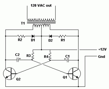
Transistor gets hot and this inverter consumes around 500 mA when a 3 watt LED bulb Transistor is screwed with a suitable size heat sink this is because the Resistance of 500 ohm which is close to 470 ohm. We connected two 1k ohm resistors in parallel which gave us an effective Medium power transistors and you may also use BD137 or BD135 and it should workĭidn’t had a 470 ohm resistor at the time of testing this circuit, so instead Is our prototype, we have tested this circuit using BD139 and D882 which are

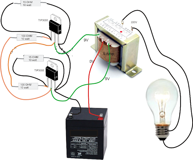
Always the primary winding will have highest resistance of the three and secondary winding is at opposite side. You can always find the correct terminals by measuring its winding resistance. Note: On some transformers the primary and auxiliary terminals could have its sides switched. Two terminals on the other side are the secondary winding through which we are It will be in the order of few ohms, we measured its resistance and it wasĪpproximately 8 ohm, which was highest of the three windings.Ĭouple of terminals at the left side are the auxiliary winding and it will be utilized You can confirm this by measuring its winding resistance using a multimeter, Probably the couple of terminals at the right side are the primary winding You and the two terminals on the opposite side away from you, as illustrated in Transformer’s terminals are most probably the same as shown above.Ĭan identify its correct terminals by holding the transformer’s four terminals towards Now you should have an idea that we are fundamentally building a crude ferriteĬore transformer based inverter that is operated at lower input voltage.įerrite core transformers are NOT readily available at retail stores or e-commerce sites, but instead we can salvage one from a DC adapter, and surprisingly we can find a ferrite core transformer easily on most commonly available DC adapters. We have designed a 12V ferrite core inverter which can deliver 500W power you can find the circuit and detailed explanation about this inverter here. Range which cannot directly utilized by all AC appliances, so the high voltage highįrequency output of ferrite core transformer is rectified and converted to standard The iron core transformers are bulky,Ĭore transformer based inverters on the other hand are very light weight whenĬompared to iron core, compact in size, offers superior efficiency and costsįerrite core transformers are operated at high frequencies like tens of KHz The name suggests it utilizes a ferrite core transformer instead of an ironĬore transformer, traditionally inverter’s step-up transformers are made using If you don’t know what ferrite core transformer based inverter is, please let us explain……. The above circuit is essentially a ferrite core transformer based inverter. the battery and a LED lamp (0.5 watt to 6 watt). The other two components are the sourceĪnd load i.e. Power NPN transistor (BD139/BD137/BD135/D882) and a ferrite core transformer whichĬan be salvaged from a DC adapter. To build one: a 470 ohm resistor, a medium Proposed inverter circuit is very simple and there are only 3 components to be collected


So, we are here to explain all the aspects of one such inverter, so keep reading on…. NOTE: There are lot of fake inverter projects online where they claim to convert 1.5V from an AA battery to 220VAC and there are real inverter projects where they do light up a 220V LED lamp using a 1.5V battery, but unfortunately there are no clear explanation about its practicality and reliability in real life circumstances and there are no explanation how the circuit works. Testing the inverter circuit at different.Where to obtain a ferrite core transformer and.

Circuit diagram of 1.5V to 220V inverter.It can be a good project for school scienceįair or as an emergency light for your room. This inverter comprises of just 3 components and even a beginner canĪccomplish this project with ease. This miniature inverter circuit can operateįrom 1.5V to 9V DC and can be used for powering small loads like 0.5 to 6 watt (120/220V) This post we are going to construct a simplest possible power inverter whose


 0 kommentar(er)
